Drawing Tool
The drawing tool allows to draw simple and complex objects in the context of the environment model or map. Clicking on the black selection arrow next to the icon opens the selection of all available drawing tools. The selected tool is highlighted in green in the upper selection bar.

The drawing tools are available in both 3D and 2D. At this point, the context menus and editing options from the 3D view are explained, in the 2D view these are also available, but with reduced functions.
Drawing objects
|
|
|
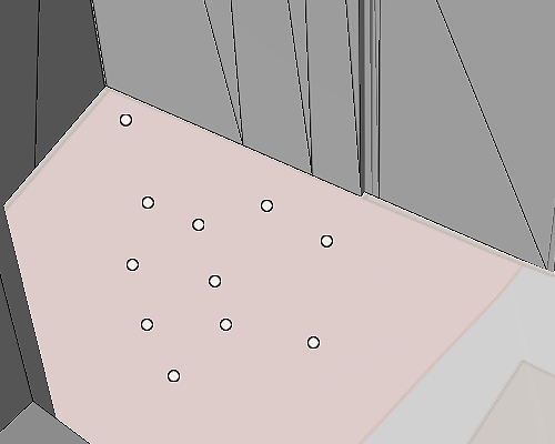
A mouse click on the desired location in the map sets a point. |
|
|
|
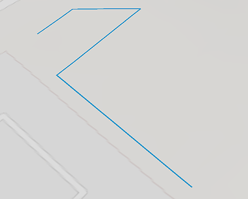
A mouse click anywhere on the map sets a point. To complete the line, the last point is set with a double click. |
|
|
|
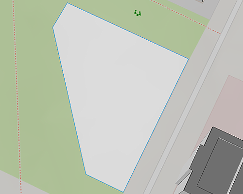
A point is set with a mouse click at any position on the map. If the mouse is then moved to the next point, a line is automatically created which can be drawn until the next point is set. Once the desired shape has been drawn by setting several points, it can be completed by double-clicking when the last point is set. Several shapes can be created next to each other. |
|
|
|
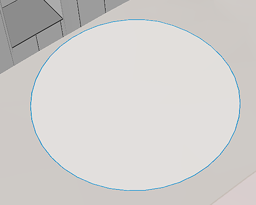
A mouse click anywhere on the map sets a point, the center of the circle. By dragging the mouse, the circle can be resized to the desired size. Another click, which sets the radius, completes the shape. |
|
|
|
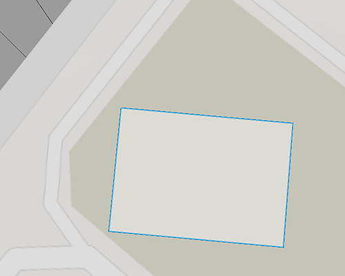
A mouse click anywhere on the map sets the upper left and lower right corners of the rectangle. These are always aligned to the north. By dragging the mouse, the rectangle can be resized to the desired size. Another click completes the shape. |
Object selection
With the arrow symbol, the selection tool on the left in the drawing tools menu, the objects can be selected individually with one mouse click. For a multiple selection, the objects must be clicked one after the other while holding down the control key (ctrl).
|
To quickly and easily select multiple objects, especially if they are located on top of other objects, for example, the selection option under |
Edit, transform, delete objects
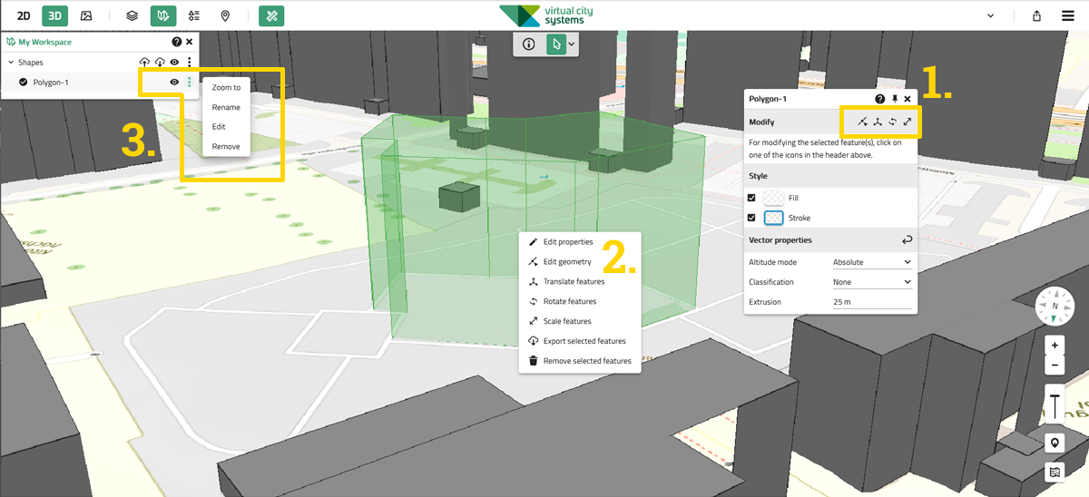
1. Via the properties window
When selecting a geometry type, a menu window opens automatically on the right side of the map, in which "Styles" for the color representation as well as "Vector properties" e.g. for the spatial representation of the drawn object can be set. This window can be moved to any other place on the map by dragging it from the upper edge with the left mouse button pressed.
Once an already drawn object has been selected, the following editing options are available in the properties window:
-
Edit geometry
-
Translate features
-
Rotate features
-
Scale features
2. Via the right mouse button
A click with the right mouse button on the corresponding object selects it and opens a context menu through which all editing options can be displayed and selected. The export function is also offered at this point:
-
Edit properties
-
Edit geometry
-
Translate features
-
Rotate features
-
Scale features
-
Export selected features
-
Remove selected features
3. Via „My Workspace“
All objects can be accessed via My Workspace in the main horizontal navigation where they can be selected, shown and hidden, edited, renamed and removed:
-
Zoom to
-
Rename
-
Edit
-
Remove
Properties window
When you select a geometry type or an object that has already been drawn, the associated properties window opens. Here, settings for drawing the corresponding geometry shape can be made or the shape can be edited subsequently. Depending on the geometry shape, different editing options are available.
If a selected object that has already been drawn is subsequently edited, the changes are immediately applied and displayed as soon as the selection of the object and thus its green highlighting has been removed.
The properties window can be moved to any position on the map at the top edge by dragging and dropping with the left mouse button pressed as soon as the mouse pointer is symbolized by a hand. With the pin symbol the window can be docked to the map again.
|
If different geometry objects are selected at the same time, the Properties window automatically adjusts to show only the intersection of setting options common to both geometry types. |
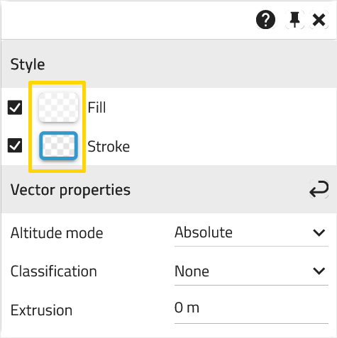
Style
Fill
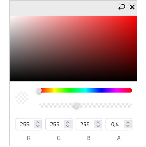
A click on the Fill icon opens a window where the color and transparency of the fill of the objects to be drawn/drawn can be adjusted.
-
The color selection can be made either by clicking in the upper color field, by using the color slider or by directly entering an RGB color value.
-
Transparency can be adjusted either by the slider or by entering a value in the "A" field.
-
No fill: To remove the fill of an object completely, the
checkmark in the box in front of the style field must be removed with a click.
Clicking on the arrow to the left of the closing
resets the settings made.
Settings for the Fill style are available for the geometries Polygon,
Circle and
Bounding Box / Rectangle.
Stroke
Clicking the Stroke icon opens a window where you can adjust the line width, color and transparency of the lines of the objects to be drawn/sketched.
-
The line width can be set via a value in the "Line width" field.
-
The color selection can be made either by clicking in the upper color field, by using the color slider or by directly entering an RGB color value.
-
The transparency can be adjusted either by the slider or by entering a value in the "A" field.
-
No line: To remove the line of an object completely, the check mark in the box in front of the style field must be removed with a click.
Clicking on the arrow to the left of the closing
resets the settings made.
Line style settings are available for the geometries Lines,
Polygon,
Circle and
Bounding Box / Rectangle.
Symbol
Clicking the Symbol icon opens a window where predefined shapes and icons can be selected as an alternative representation of the point marker. Radius, lines and fill style can also be adjusted for the shapes, or transparency and size for the icons. If a point is to be adjusted later, it must be selected beforehand.
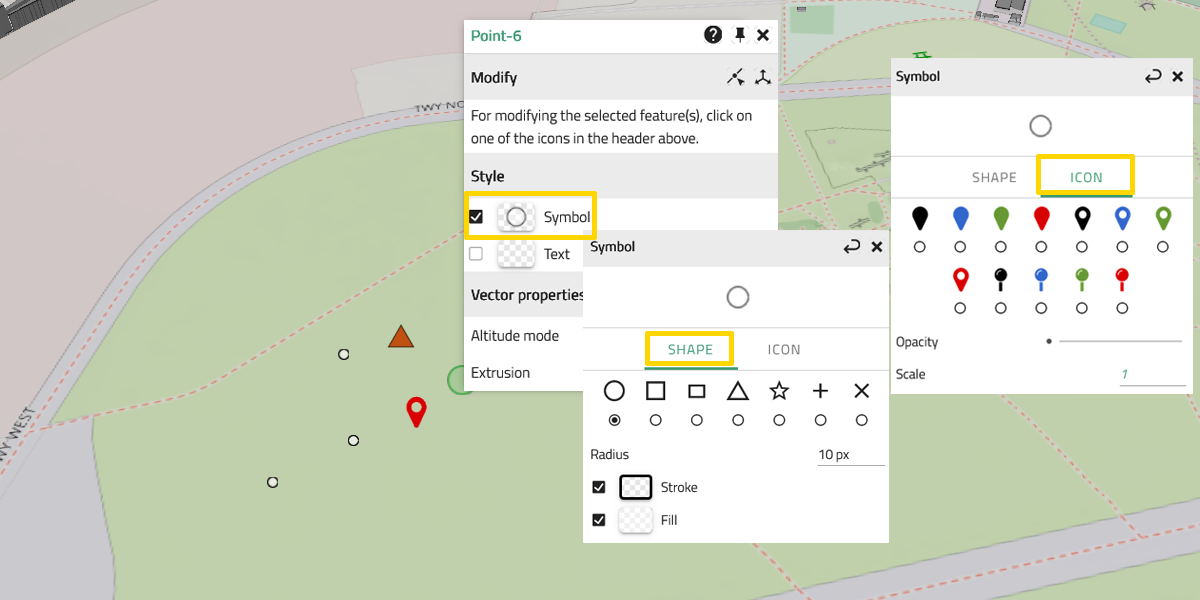
Clicking on the arrow to the left of the closing
resets the settings made.
These settings are only available for the geometry Point.
Text
When selecting the geometry type Point, the additional option of text input is available. A point can therefore be set directly with a label. To do this, the check mark must be set in the box in front of the empty preview image Text. Now the text option is activated, a click on the
text icon opens the settings window for text formatting. Here the text can be entered, font type and size can be chosen and other style elements can be selected. The offset can be used to move the text by entering X and Y values. Entering a negative Y value shifts the text upwards.
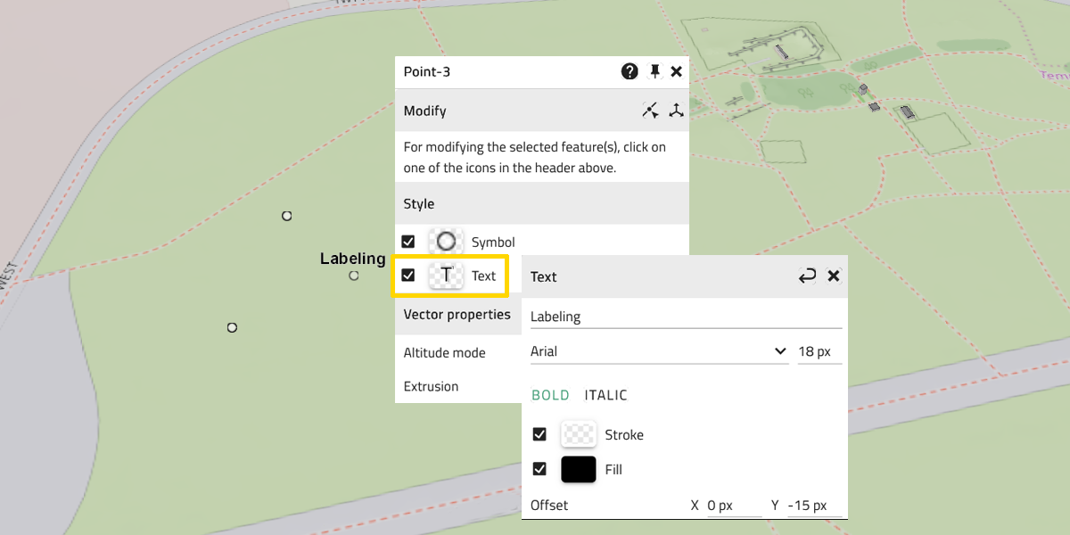
A label can be added later to points that have already been set; to do this, the point object must be selected beforehand.
Clicking on the arrow to the left of the closing
resets the settings made.
These settings are only available for the geometry Point.
Vector properties
Extrusion
|
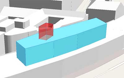
To generate solids from planar objects, they can be extruded by any height. For this purpose, a meter must be entered in the corresponding field. |
Altitude mode
|
Two height modes are available for drawing objects: Relative to ground: Absolute: |
Classification
For the classification of objects, the following options are available:
-
None:
This is the default setting. No classification is undertaken and and therefore, the object is rendered normally. -
Both:
The object is used to classify both terrain and 3D Tiles (3D Mesh, building data sets, ect.). The intersections of the object in question and the terrain or a 3D Tile are highlighted. -
3D Tiles:
The object is used to classify 3D Tiles. The intersections of the object in question and a 3D Tile are highlighted. -
Terrain:
The object is used to classify the terrain. The intersections of the object in question and the terrain are highlighted.
Please note: If the object does not intersect any surface to be classified, it will not be displayed!
All objects can also be placed on the terrain.
