Planning editor
The planning editor allows the user to design and persist a planning project. The Planning editor window or the Planning toolbar can be used for this purpose.
The VC Planner plugin provides the user with several functions / categories that can be called up both via the planning editor window and via the planning tool, see also the image above.
Planning editor
Basic functions
The planning editor follows the basic principle of VCS window technology and, in addition to help, also offers the option of undocking the window from its original position and moving it to another position.
| Function / Icon | Description |
|---|---|
closes the window, but leaves the selected planning active. Clicking on the planning icon in the header opens the window again at the old position. |
|
depending on the category on which the |
|
Depending on the category on which the - Select all |
|
indicates unsaved changes. The icon can appear either on objects or on buttons. On objects or layers, the icon shows which objects / layers have been changed since the last save. On the Save button, the icon indicates that there are changes that should be saved, see the graphic above. |
|
Clicking on |
Extended functions on elements within a category
| Element in Category | Functions |
|---|---|
Viewpoints |
|
Camera flights |
|
3D models |
|
Vector layers |
|
Raster layers |
|
Hidden objects |
|
measurement modification |
|
Tasks |
|
extended functionality on right click in map
| Element in Karte | Funktionen |
|---|---|
3D Model |
|
Vector object |
|
Meshmodification |
|
categories and editors
See also further information on the individual editors:
Hidden objects
All hidden objects are listed here. Clicking / selecting an element in the list displays the selected object transparently in the map. Clicking on offers the option to remove the element from the list "Delete element " and thus make it "visible" again. It is important to note that this does not delete the element from the data set, but the entry from the list of hidden objects, thus making the object visible again.
Tasks / Tasks
Running or failed conversion tasks are listed under Tasks. After data has been uploaded to the planning project via the data upload dialog, a conversion job is triggered in the Planner backend. Both running and failed conversion jobs are displayed under Tasks / Tasks. Successful conversion jobs no longer appear in this list, but are listed as data records / levels in the corresponding category. Failed conversion jobs are highlighted in color and marked with an icon.
Planning toolbar
Description of the tools in the graphic above, from left to right:
| Tool | Description |
|---|---|
Info |
activates the Info-Tool and shows a balloon for a selected object. |
Upload |
opens the Upload dialog (Raster data, Vekcor data, 3D Model). Raster data, vector data and 3D models can only be imported via Toolbar / Uploadbutton. |
The Draw button |
can be activated by selecting a vector layer in the Planning Editor - Vector Layer and activates the corresponding drawing functions. The other drawing tools are displayed via |
Object library |
is activated by selecting a vector layer in the planning editor - vector layer and clicking on the icon opens the object library editor |
Viewpoint |
Opens the viewpoint editor |
Camera flight |
Opens the camera flight editor |
Hide objects |
Clicking on the icon activates the function directly and clicking on an object hides it and adds an entry (object ID) in the "Hidden objects" category in the planning editor |
Measurement modification |
Clicking on the icon next to |
Comment function |
Click on the icon to activate the comment function. Clicking in the map at the desired position sets a comment marker and opens the comments editor. |
The planning editors in detail
Viewpoints
This editor is used to configure viewpoints. Views are used to allow users to quickly jump to predefined perspectives.
Clicking on adds a new view and opens the interactive view editor.
Clicking on sets a view as the start view.
Whenever the application is loaded, the map section is loaded according to the defined start view.
| The Position and Orientation areas are controlled interactively by the camera according to the WYSIWYG principle and change as you move around the map. Conversely, if values in these areas are changed, the current camera view automatically adapts to the changed information. |
The following parameters can be configured for the respective view:
General settings
| Option | Description |
|---|---|
Name (ID) |
Unique name (identifier) of the included view. |
Title |
Display title of the included view. Is used for display in other elements that reference the view. |
Animation |
Determines whether an animation takes place as a flight between two perspectives when the view is changed, or whether the next view is loaded directly. |
Animation duration (if Animation active) |
Determines the duration of the animation in seconds. |
Position
| Option | Description |
|---|---|
Camera position |
The position of the camera in 3D space. Only displayed if the 3D map is active. |
Orientation
| Option | Description |
|---|---|
Azimuth |
Azimuth angle of the camera |
Pitch |
tilt angle of the camera, i.e. the rotation around the y-axis running in the longitudinal direction of the camera. |
|
Add adds the viewpoint to the list of viewpoints. Cancel discards the settings and closes the editor. |
Camera flights
The Camera flight editor allows you to create virtual sightseeing flights in a VC Map app. Click on the icon in the toolbar or in the "Camera flights" category to activate the editor and open the associated settings window, which can be used to create a new scenic flight.
Player
The player allows you to play the current camera flight. The time on the left-hand side of the slider indicates the current progress, the information on the right-hand side refers to the total duration.
| Action | ..UI | Shortcut |
|---|---|---|
Play/Pause |
|
This option will be available soon. |
Rewind/Forward |
|
This option will be available soon. |
Jump to last/next base position |
|
This option will be available soon. |
|
Add - adds the flight to the camera flight category Cancel discards the settings and closes the editor. |
3D models
This editor is used to configure 3D models. 3D models are used to illustrate the planning in 3 dimensions and thus give the user / viewer a more realistic impression of the planning. The editor allows the user to place / position a 3D model in 3 dimensions in the context of its environment.
| The areas Position and Orientation are controlled according to the WYSIWYG principle and change when the model is moved on the map. Conversely: If values in these areas are changed, the current position of the model automatically adjusts to the changed information. |
The following parameters can be configured for the respective 3D model:
General settings
| Option | Description |
|---|---|
Name (ID) |
Unique name (identifier) of the integrated model. |
Description |
Description of the integrated 3D model. |
Position
| Option | Description |
|---|---|
Position (input fields) |
The position of the 3D object in 3D space. The coordinates can be entered in X [°], Y [°] and Z [m] direction. |
Position (icons) |
|
Orientation
| Option | Description |
|---|---|
Azimuth |
Azimuth angle [°] of the 3D model (input value or setting via slider) |
Inclination |
Inclination angle [°] of the 3D model, i.e. the rotation around the y-axis running in the longitudinal direction of the 3D model (input value or setting via slider). |
Roll angle [°] of the 3D model, i.e. the rotation around the x-axis running in the longitudinal direction of the 3D model (input value or setting via slider). |
Scaling |
Metadata
If extended metadata has been configured, it will be displayed here and can be edited by clicking on .
You can find more information on this at Setting / editing of extended metadata and Planning object / planning feature - Set / edit metadata
|
Apply accepts the settings for the 3D model and adds it to the list of 3D models Cancel discards the settings and closes the editor. |
Vector layer
General settings
| Option | Description |
|---|---|
Name (ID) |
Unique name (identifier) of the integrated layer. |
Description |
Description of the integrated layer. |
layer settings
| Option | Description |
|---|---|
Z Index |
Setting the Z-index of the layer, see also z-Index (display order) |
vector properties
| Option | Description |
|---|---|
Elevation mode |
Defines the elevation mode used. 'On terrain' places 2D data on the terrain. 'Relative to terrain' interprets heights as values above the terrain. 'Absolute' is the 3D height above the reference ellipsoid. |
Height above ground |
A vertical offset to the terrain. Can be used with height mode 'Relative to terrain'. |
Terrain level |
Terrain height of the objects. |
Distance Scaling |
Determines or sets scaling properties of objects based on the distance of the object to the camera. Interpolation of the object scaling between the specified distances. Outside these ranges, the scaling of the object remains fixed to the nearest limit. If not selected, no scaling is performed. |
Eye offset |
Reads or sets the Cartesian 3D offset applied to objects in eye coordinates. Eye coordinates are a left-handed coordinate system where x points to the right, y points up and z points into the screen. Eye coordinates use the same scale as world coordinates, usually meters. An eye offset is often used to arrange several objects in the same position, e.g. to arrange an object above the corresponding 3D model. |
Allow selection |
Determines whether features can be selected, e.g. to display feature information. |
Classification |
Defines what is affected by the classification, i.e. only "objects", only "terrain" or "objects & terrain" are classified. The default value when adding a layer is "none". |
Extrusion |
Defines the default extrusion height of objects. Only supported with 'absolute' height mode. |
Storeys above ground |
Number of storeys above ground. Requires either 'Extrusion' or 'Floor height(s)'. |
Storey height(s) above ground |
Values for the storey height(s). Starting with the first floor if more than one is specified. The last entry is repeated if fewer 'Storey height(s)' than 'Storeys' are specified or until the 'Extrusion' is reached. |
Skirts |
Sets the default extrusion (depth) of objects below ground level. |
Skirts below ground |
Number of floors below ground. Similar behavior to 'Storeys above ground'. |
Storey height(s) below ground |
Values for the storey height(s). Starting with the first basement floor if several are specified. The last entry is repeated if fewer "Storey height(s)" than "Storeys" are specified or until basement depth ("Skirt") is reached. |
Model URL |
Relative path to the standard model that is applied to point objects. Supported format is GLTF ('.gtlf' or '.glb'). |
Model scaling |
Defines the standard scaling in x, y and z. Values greater than 1.0 enlarge the model, values less than 1.0 reduce it. |
Model orientation |
Orientation is the rotation around the negative z-axis. |
Model Inclination |
Inclination is the rotation around the negative y-axis. |
Rotation |
Rotation is the rotation around the positive x-axis. |
Base URL |
A base URL to resolve relative model URLs. Expects http or https requests. |
| The vector properties configured here define the default behavior of the layer. Each feature can have its own properties that override the values of the layer. |
| Please bear in mind that vector layers are limited in terms of performance, especially when displaying models, as there is no tiling. |
Metadata
If extended metadata has been configured, it will be displayed here and can be edited by clicking on .
You can find more information on this at Setting / editing of extended metadata and Planning object / planning feature - Set / edit metadata
|
Apply accepts the settings for the vector layer and adds it to the list of vector layers Cancel discards the settings and closes the editor. |
Raster layer
General settings
| Option | Description |
|---|---|
Name (ID) |
Unique name (identifier) of the included raster layer. |
Description |
Description of the included raster layer. |
Position
Option |
Description |
Position (Icons) |
|
Projection |
Specifies the projection of the bounding box of the raster layer. This is set to 'EPSG:4326'. This means that the corner coordinates are always specified in latitude and longitude coordinates on the WGS84 reference ellipsoid. |
Min |
Coordinates (Lon/Lat) of the lower left corner of the bounding box. |
Max |
Coordinates (Lon/Lat) of the upper right corner of the bounding box. |
Layer settings
Option |
Description |
Opacity |
Defines the transparency of the layer in a value range between 0 and 1. A value of 0 corresponds to complete transparency, a value of 1 to complete opacity. |
Z Index |
Setting the Z-index of the layer, see also z-Index (display order) |
Metadata
If extended metadata has been configured, it will be displayed here and can be edited by clicking on .
For more information, see Setting / editing of extended metadata and Planning object / planning feature - Set / edit metadata
|
Apply accepts the settings for the vector layer and adds it to the list of vector layers Cancel discards the settings and closes the editor. |
Mesh modification
Selecting a modification mode in the toolbar and drawing a polygon or selecting an element in the "Mesh modification" category opens the mesh modification editor.
The editor uses both available modes:
-
Flatten mesh - here the mesh is flattened (textures and geometry are retained, only the Z coordinates are changed to the specified value); please enter a value for Absolute height
-
Cut mesh (cut) - here the polygon is used as a cut polygon and the geometry is cut open at the edges
Both modes support geometry editing - move and edit interpolation points. In addition, the plane or planes for which the modification is to be applied can be selected.
Object library
| The object library editor can only be opened once a layer has been selected in the vector layer category. This activates the object library icon in the toolbar and makes it available to the user. This enables structured working. For example, a trees layer can be created, selected and then the corresponding trees can be placed using the object library. |
The object library editor provides 4 categories (collapsible / expandable).
-
Object library - Selection of the corresponding library and display of the elements (a click on an element selects it and a click in the map places the element at the desired position)
-
Edit name & description - Edit / set name and description of the vector layer
-
Vector properties - see also Vector properties Edit metadata - For more information, see Setting / editing of extended metadata and Planning object / planning feature - Set / edit metadata
z-index (display sequence)
The z-index defines the rendering sequence of an image planning object or a vector layer (feature store object) within a planning project. Depending on the specified z-index per object layer, the user can define the display sequence of the individual layers manually.
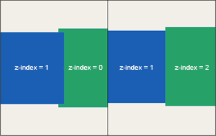
For example, a layer with a higher z-index is always rendered above a layer with a lower z-index. Various, but not all vector and raster layers support z-indexing.
Supported drawing objects are:
-
Line, Polygon, Bounding Box, Circle, Rectangle and Text Label
-
Supported vector layers are: .shp, .kml/.kmz, .json/.geojson
-
Supported raster layers are: .png, .jpg/.jpeg, .tif/.tiff/.geotiff
The z-index can be set in the planning editor in vector and raster layers. By default, each new layer has a z-index of 0.
In practice, each newly loaded layer will overlay a previously imported layer with the same z-index. To change the display order of the imported layers with the planning tool, the user can change the z-index in the editing section of the respective planning project.
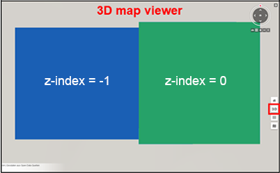
The user can also set the z-index with a negative number. This works in the same way as with positive numbers, the lower the number, the lower the placement (display).
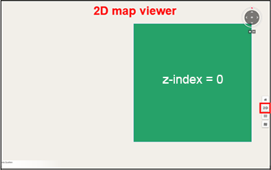
| Please note that in the 2D map view layers with negative z-indices are placed below the base map. |
In the 3D map view, however, a raster or vector layer with a z-index lower than 0 can only be placed above the base map due to the interface used for the 3D visualization (Cesium). The behavior of the layers in the different map views is illustrated below.
|
|
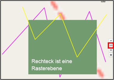
| The order of the z indices in the 3D map view can only be maintained within the same layer type. This means that raster layers are always overlaid by vector layers, regardless of their z-index. Within the same layer type, the z-index and thus the placement sequence of the layers is maintained as already explained. In the 2D map view, however, the z-index is also taken into account between raster and vector layers, so that the placement sequence between all layer types is chronological according to their z-index. For a better understanding, please refer to the following two illustrations. |
|
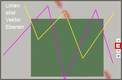
|
Data upload
The data upload, as shown above, is valid for the upload of vector and raster data, as well as 3D models.
The upload dialog provides an area where files can be dragged and dropped. In addition, a file explorer can be opened by clicking on , which allows the data to be uploaded to be selected and made available for the import process.
Click on Import to start the upload and then the corresponding conversion process.
Clicking on Cancel discards the files from the upload dialog and closes the window.

